Impedance models for the collider at 10 TeV center of mass #
The first component studied for the collider impedance model is the vacuum chamber. We assume for now that the vacuum chamber is identical for all the accelerator. Also the Twiss beta functions are assumed constant along the ring.
Simple models (single layer of materials, with infinite thickness) were first studied. A study of the minimal chamber radius achievable without beam instability was performed with the these impedance models.
Simple impedance models scans #
Several materials were first investigated for the collider ring impedance
Assumptions for the impedance model #
We assume a circular beam chamber with different radius from 5 mm to 50 mm. Different material are also investigated: Copper at 300 K, Copper at 80 K, Tungsten at 300 K, Tungsten at 80 K. The chamber and material parameters are reported in the tables below.
Chamber geometric parameters:
| Item | Unit | Value |
|---|---|---|
| Machine | / | COLL10TeV |
| Total machine length | m | 10000 |
| Average beta function (x/y) | m | 85/51 |
| Chamber length | m | 10000 |
| Chamber geometry | / | Circular |
| Chamber inner radius | m | From 5 mm to 40 mm |
| Chamber material | / | Copper 300 K / Copper 80 K / Tungsten 300 K / Tungsten 80 K |
| Chamber thickness | m | Inf |
The materials used have the following properties:
| Material | DC Resistivity / Ohm m | epsilonr |
|---|---|---|
| Copper 300 K | 17.9e-9 | 1 |
| Copper 80 K | 1 | |
| Tungsten 300 K | 55.6e-9 | 1 |
| Tungsten 80 K | 6.06e-9 | 1 |
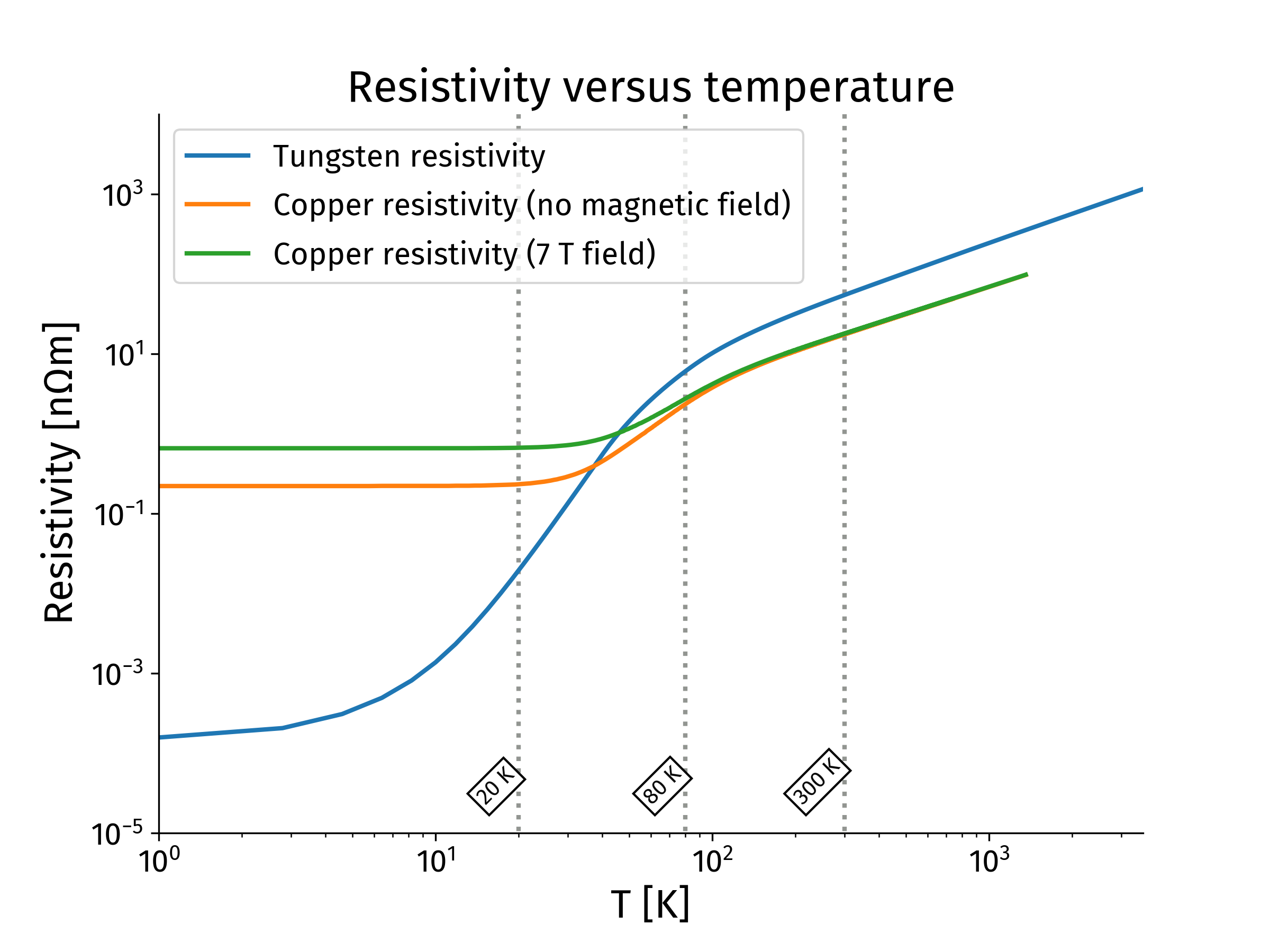
Material resistivity dependency versus temperature is implemented in the impedance toolbox. Copper also includes depedency with magnetic field.
Copper was first chosen as it is a common coating for beam pipe when electrical conductivity is a concern.
Tungsten would be used as magnet liner to absorb muon decay products and avoid excessive heating of the cold bore(see for example N.V. Mokhov et al., 2018, JINST 13 P10024 or M. Green, 1996, Nuclear Physics B, 51 1 pp. 158-167).
Results of the scans with pure materials #
Several beam pipe radius were scanned, between 10 mm and 40 mm. Results are plotted below for the two extrema radii and the different materials considered.
Second impedance model investigation: copper coating on tungsten at 300 K #
A copper coating applied on the tungsten shield is a way to reduce the impedance and therefore increase the stability threshold. A scan on the copper coating thickness applied on a tungsten at 300 K shield was performed, the plots below show the resulting impedance for a 20 mm innermost chamber radius.
Chamber geometric parameters:
| Item | Unit | Value |
|---|---|---|
| Machine | / | COLL10TeV |
| Total machine length | m | 10000 |
| Average beta function (x/y) | m | 85/51 |
| Chamber length | m | 10000 |
| Chamber geometry | / | Circular |
| Chamber inner radius | m | From 10 mm to 40 mm |
| Material layer 1 | / | Copper 300 K |
| Thickness layer 1 | m | 0.1 um to 500 um |
| Material layer 2 | / | Tungsten 300 K |
| Thickness layer 2 | m | Inf |
The materials used have the following properties:
| Material | DC Resistivity / Ohm m | epsilonr |
|---|---|---|
| Copper 300 K | 17.9e-9 | 1 |
| Tungsten 300 K | 55.6e-9 | 1 |
Several beam pipe radius were scanned, between 10 mm and 40 mm. Results are plotted below for the two extrema radii and the different materials considered.